Drains, Culverts and Races for the Great North Road
In the section on Road Construction Technology for the Great North Road, reference was made to public demand for better roads in England of the early 19th Century. They were fed up with the founderous ways. A road was made of a mound of earth, meant to be drained by its convexity. Carriage wheels turned the surface into slots of mud and water, the roads were too narrow and disastrous accidents occurred when vehicles tried to pass one another. Thomas Telford and John Loudon MacAdam were the two men who reported to the Select Committee of the House of Commons, giving evidence of their experiments on properly engineered roads. A key issue in their evidence was drainage, the dispersal of water into drains and culverts so that the roadway itself remained a hard dry surface. MacAdam, who became the Surveyor General of Bristol, produced his report for the Select Committee in 1819 and he maintained that no greater convexity should be given than enough to cause rainwater to run easily into the side-drains. By 1823, MacAdam was able to write his Remarks on the Present System of Road Making in England.
… it is the native soil which really supports the weight of traffic; that while it is preserved in a dry state, it will carry any weight without sinking.
It is evident that the military men who took the role of being the Surveyor of Roads and Bridges, such as Major Edmund Lockyer, were aware of the improved technology for road making in Britain. In 1828 soon after his appointment to this position, he issued detailed instructions to Assistant Surveyors in the various areas under his command. In them, there is the following order which reflects MacAdam’s principles: … one mode of keeping roads in good order is to keep them dry, that is that the water must not lodge on them or against them. The drains cut at the sides already prove the great good of them.
He did not give any direction about the construction of the drains. There were considerable variations in the cutting of them along the whole length of the GNR. No doubt, the design of each depended on the site, the local road gradient, an estimate of the amount of water which might have to be removed and the growing experience of the Assistant Surveyors themselves, such as Lieutenant Percy Simpson, Heneage Finch and others later on the road from Wollombi to Newcastle.
In 1828, Assistant Surveyor Percy Simpson was using MacAdam’s road building principles, with the emphasis on effective drainage. He was organising the formation of side-drains, culverts across and under the roadway, and races to carry the water effectively away from walls. Each of these operations is treated in separate sections.
Drains and Drainage for the Great North Road
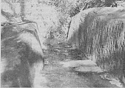 A hand cut drain along the Great North Road.
With the background of turnpike development in England, drainage was going to be of major importance to the Assistant Surveyors on the great roads envisaged by the Surveyors General and the Governors of the time. While it may have seemed, early on, that the new colony was to have serious droughts and water shortages, it had become very apparent that there were times when heavy rain would fall and stormwater flooding would develop. From investigations of the history of the Great North Road by Dr Grace Karskens, side drains would have been used along the whole length of the road. Drains would have been on both sides in flat land and on the uphill side where the road was constructed along a slope such as at Devine’s Hill Ascent.
Although there was no uniformity in the design of the side-drains, the Assistant Surveyors must have used their judgement about what should be used. Where the land was near level and there was not rock alongside the roadway, the drains were cut from the earth and, in some instances, timber slabbing was used along the sides and in the bottom. These earth drains and timbered ones have almost all disappeared through rotting of the timber and erosion by soil though some can still be seen. Where there was rock such as on the uphill side of Devine’s Hill, the drains were cut from the rock using chisels and picks, with the remaining rock bearing the marks of this work. These can be seen on the Devine’s Hill Ascent.
Ian Webb points out that an instruction was issued in 1830 from the Roads and Bridges Department, stating the dimensions for side-drains should be 2 feet 2 inches (660 mm) at the top, 1 foot 1 inch (330 mm) at the bottom and 1 foot 10 inches (560 mm) deep. He considered that this must have been for drains dug in the soil because the side-drains cut in the rock at the base of cuttings did not have these dimensions. Karskens (Ref.1) comments that the surviving side-drains vary considerably in size with depths from 50 mm to 600-900 mm and widths between 300-1200 mm. The most sophisticated drains include low walls or edging of one to two courses of stone, aligned with the roadway. One can only conclude that decisions were made on the spot at the time of construction.As we shall see later, the volume of water coming down the drains during a rainstorm could often be considerable, especially on long gradients such as at Devine’s Hill so that there had to be many channels provided across the roadway to clear it. These were the culverts of which as many as 51 of various sizes and constructions have been located up Devine’s Hill Ascent from the Hawkesbury River end to the junction with the Finch Ascent.
Culvert Construction for the Great North Road
Side-drains were an essential part of the road design but means for the water to be led away into gullies, creeks and valleys was of equal importance. For example, an uphill side-drain needed to be emptied across the road line onto the valley side. In a flatter countryside, both side drains had to empty somewhere; depending on the lie of the land, at least one side-drain would have to discharge under the road. The drains also had to be kept clean of soil, leaves and twigs. The Assistant Surveyor would have had to use his experience and judgement to decide how big the drain should be and how the flowing water could be conducted to a place where it could discharge without causing erosion to the road and on the roadside. The design of culverts for the road in many places became a matter for continuing consideration because it was necessary to construct them from the materials readily available at the particular site – stone, timber or a combination of these.
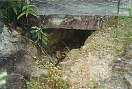
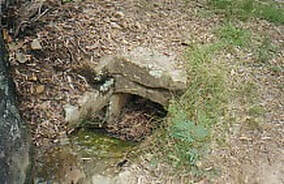
When work began on the road to the Hunter Valley in 1826, the walls and drainage structures were scarce, crude and poorly built.Culvert along Great North Road Convict Trail Project In 1827, the works were under the supervision of Lieutenant Jonathon Warner at Wisemans Ferry. The picture of a culvert outlet and the retaining wall shows the small scale of the outlet and the low standard of the work in both culvert outlet and wall. At least, the idea that drainage was a necessary part of the road construction was in place but more needed to be done to raise the standard of work. The impact of the transition to supervision by Lieutenant Percy Simpson was soon become evident in the structures that he put in place, with clear and active help from his overseers and road parties.
As work began under Lt. Percy Simpson and Heneage FInch, construction of the culverts and their inlets and outlets took on variations in design to meet the requirements of drainage, depending on the gradient of the roadway under development. Culverts of stone, such as on the Devine’s Hill Ascent, were set either at right-angles to the line of the roadway or at an angle between 130 and 145 degrees to that line. As Karskens notes, such oblique culverts would be between 25 feet (7.7 m) and 45 feet (13.8 m) in length across the road.
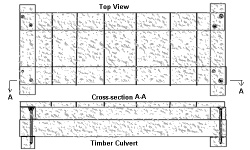 Timber culvert design.
Webb comments that the culverts ranged in size from large enough to crawl through to as small as 400 mm by 320 mm. In September 1830, the No.25 Road Party constructed on Devine’s Hill a culvert 15 yards long walled both sides, flagged top and bottom and covered 2 feet in the road. After digging the trench, the bottom was lined with split stone slabs butted together to form a solid base. From the dimensions given, the slabs would have weighed around one and a half tonnes. It is not evident what method was used to carry, lift and place in position such huge slabs. Some form of lifting tackle must have been available since a block of stone of one and a half metres in length, a metre in width and 30 cm thick would not have been lifted into place by, say, six men shoulder to shoulder. But it was done and done accurately. The sides were also of split stone, set on each side of the trench, bedded onto the large slabs. Finally split stone slabs were set across the top to form the culvert. Webb comments that, during repair work in the mid-1980s, a culvert of this design was repaired. It was found that some of the top stone slabs had been bedded onto the side walls with clay in which small flat stones had been placed to prevent the top slabs rocking when vehicles passed over the road. This is the only known example of a form of mortar used as all the other blockwork in walls and bridges was dry laid. There were as many as 51 culverts of various sizes, with varying construction methods used, on the Devine’s Hill Ascent
Webb gives an interesting account of the use of timber for culvert construction where suitable stone was not available. Squared timber logs and split timber slabs were used in the construction, with the logs held together by iron spikes of around 20 mm in diameter and up to 500 mm in length. The sketch gives some idea of the construction of such culverts. He notes that only a few timber culverts remain intact to carry water under the road; most have collapsed with the timber rotting away (eaten by white ants?) and even burnt out by bushfires.
The inlet and outlet entrances to culverts gradually developed from the rather elementary designas shown above into quite sophisticated ones that are discussed next.
Culvert Inlets & Outlets
In the previous section on culverts, we saw that the rather elementary inlet and outlet to the culvert under the road were built into the walls with a stone block on either side of the opening and a rather ragged stone lintel across the top. Once again, we draw attention to the increasingly sophisticated inlet and outlet stonework for the culverts introduced by Simpson with his overseers and his convict gangs and, later, Heneage. The work of No.25 Road Party is evident on the culvert work on the Devine’s Hill Ascent.
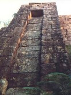
On the uphill side of the ascent, there are a various entrance designs to the culverts from the rock-cut drains. Three of these have been included in the images below. The lintels are quite different and it may be that the drains were of different widths where the culverts were located.
On the outlet side, especially on downside of the road in the Devine’s Hill valley, it had been considered necessary for a massive wall to be erected with buttresses to support it. The buttresses had a culvert outlet near the top with a race for the water to cascade down without eroding the valley slope itself. The rate of water flow that the drain, culvert and race would have to cope in a rainstorm was considerable as we shall show.
These culvert outlets were of a fine design, worked into the wall with carefully fitted stonework. In all, the design and fabrication was well thought out and made up of very sophisticated stonework.
The work was performed under Simpson’s direction and probably to his design, by his overseers and his road party convicts. We can only pay tribute to them for the beautiful work they did and must ensure that generations following us will be able to view their handiwork.
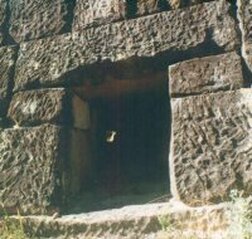
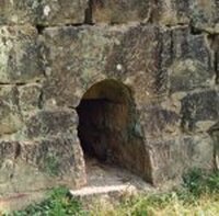
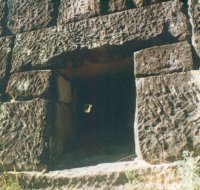
This outlet is also in the Devine’s Hill Ascent. It gives a picture of the carefully picked finish to the stones, with the very large, rectangular lintel, sitting on some well-set vertical support stones. What is interesting about this photograph is that, a long way in the distance through the culvert, it is possible to see sunlight reflected into the drain at the inlet end. The culvert is not at right angles to the road alignment in this instance. From the picture, it runs uphill by as much as thirty degrees from directly across the road. The flow of the water down the drain would have been less impeded in its turn into the culvert at less than ninety degrees. There is also a definite slope down from the inlet end to the outlet to assist the water flow. Once again, there was careful attention to detailed design to meet the drainage requirements.
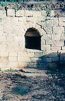
Proceeding north along the Great North Road past Mt Baxter Ascent, Hungry Flat, Sawyers Gully, up Sampson’s Pass, we come to Bucketty where there is much of interest. However, let us proceed towards Laguna House until we come to Fernances Crossing where there is a culvert entrance which has a semicircular arch.
Proceeding north along the Great North Road past Mt Baxter Ascent, Hungry Flat, Sawyers Gully, up Sampson’s Pass, we come to Bucketty where there is much of interest. However, let us proceed towards Laguna House until we come to Fernances Crossing where there is a culvert entrance which has a semicircular arch.
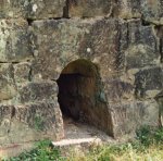
The culvert entrance at Fernances Crossing (above left) has a semicircular arch. What has been something of a mystery is that about 2km further on is the Murrays Run culvert, built through a similar sized gully to that at Fernances Crossing. Its culvert entrance has a semicircular arch also but its design and structure are completely different. The Fernance Crossing lintel is made of a large block of stone with an arch cut into its bottom side.
The Murrays Run arch has what are known in architecture as voussoirs, the wedge-shaped stones forming the arch with the joints between them forming a lines which go radially through the centre of the semicircle (roughly in this case).
The Murrays Run arch has what are known in architecture as voussoirs, the wedge-shaped stones forming the arch with the joints between them forming a lines which go radially through the centre of the semicircle (roughly in this case).
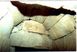
At some stage, possibly later than the 1850s, the road was widened, from 16 ft 6 in to 26 ft 6 in, at Fernances Crossing. Those doing the work made the heavy lintel stone with the semicircular arch cut from it. Trevor Patrick, mentioned in the section on the convict medical chest, crawled inside the culvert some 3 m and photographed the more elaborate work of the original culvert arch. It is built with voussoirs with lintel stones beneath helping to support the arch. This arch is thus very similar to the Murrays Run culvert arch with its voussoirs. The pictures shows the original arch looking down the rest of the culvert and a closeup of the arch itself. We do not recommend that others crawl inside to see this detail.
It is worth finishing this section with a note from John Rigg, an enthusiastic CTP History Group member from Port Macquarie. On a visit of a few days to St Albans, there was continuous rain but it did occur to him that very few people would have seen the drains and culverts of the road up Devine’s Hill in operation. It became apparent to him, walking through the rain that the culvert system bore testimony to the work of clever surveyors and engineers, highly skilled stonemasons, overseers and convicts. Instead of flowing over the roadway, the water was diverted into the carved drains, through the box culverts to spill out in cascades from the culvert outlet over its spillstone, channelled by the stone races and out into the valley where it would do no harm to roadway or walls. John listened to the soundscape of the road, the gushing cascades, the resonance of water through the culverts and the sound of streamlets percolating down the gullies. One person in his imagination would have experienced such wet times – Baron Von HŸgel. The Baron would have heard not only these sounds but others that no longer can be heard on that road – the stentorian voice of the bullocky driving his team; the traveller or clergyman steadying his steed in the wet conditions.
It is worth finishing this section with a note from John Rigg, an enthusiastic CTP History Group member from Port Macquarie. On a visit of a few days to St Albans, there was continuous rain but it did occur to him that very few people would have seen the drains and culverts of the road up Devine’s Hill in operation. It became apparent to him, walking through the rain that the culvert system bore testimony to the work of clever surveyors and engineers, highly skilled stonemasons, overseers and convicts. Instead of flowing over the roadway, the water was diverted into the carved drains, through the box culverts to spill out in cascades from the culvert outlet over its spillstone, channelled by the stone races and out into the valley where it would do no harm to roadway or walls. John listened to the soundscape of the road, the gushing cascades, the resonance of water through the culverts and the sound of streamlets percolating down the gullies. One person in his imagination would have experienced such wet times – Baron Von HŸgel. The Baron would have heard not only these sounds but others that no longer can be heard on that road – the stentorian voice of the bullocky driving his team; the traveller or clergyman steadying his steed in the wet conditions.
Water Dispersal – From Drain to Culvert Outlet & Race
In the section on drains and culverts, we have already seen how the work of clever surveyors and engineers, highly skilled stonemasons, overseers and convicts were able to make allowance for the quantities of water which would come down in a rainstorm. Instead of flowing over the roadway, the water was diverted into the carved drains, through the box culverts to spill out in cascades from the culvert outlet over its spillstone. From there, it was channelled by the stone races and out into the valley where it would do no harm to roadway or walls. John Rigg was able to photograph such circumstances with delightful effect. It is now time to look at the races which conducted the water away from the road and the walls of structures supporting it.
 Culvert with water flowing out of it.
In the photograph, the spillstone extends beyond the line of the wall to ensure that the water falls in a cascade onto other stonework instead of running down the wall itself causing erosion. One of the design factors in setting the spillstone would have been to estimate the extension beyond the wall to produce a good clearance. The water still had to be conducted away in some sort of spillway or gutter and that is where the assistant surveyor had to take into account the way the land fell away from the structure through which the culvert had been placed. It is worth starting with places where the land fell away sharply from the prepared road, as on the Devines Hill section.
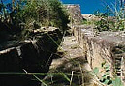
It is interesting to start with complex culvert exits and spillways. Those would have to be the spillways which were built into Devines Hill buttresses to let the water cascade down the spillway and into a stone-walled race at its base. The buttress with its culvert exit has been shown in the earlier culvert exit section. In the photograph shown, taken from the valley end of the race with the buttress in the distance, the assistant surveyor has realised that the flow of water in a rainstorm would be great so that the channel is wide and well constructed with a stone base and stone side walls
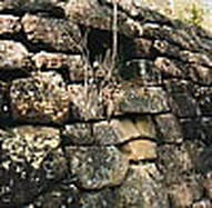
The picture is the spillway from a culvert exit on the Mt Baxter section of the Great North Road between Clare’s Bridge and Hungry Flat. There are many examples of spillways from culvert exits along this part of the road where the land fell away from the roadway.
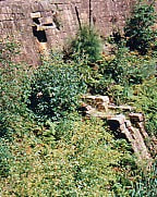
Where the water falls less height from the culvert exit than on the Devines Hill buttresses, there are, as it were, steps over which the water would cascade down. That is the case in the Ramsays Leap spillway shown in this picture. Although rather obscured by greenery, the way down from the culvert exit is evident. The stonework in the wall structure, the culvert exit and that forming the spillway are clearly of a high standard. This work would have come under the supervision of Heneage Finch who, by that time, was the assistant surveyor in charge of the work around the Wollombi area.
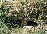
As the road proceeded north, the countryside was less mountainous along the actual route and there are further examples of culverts where it was only necessary to conduct the water away on what was essentially a creek bed. The pictures above, have been taken on the culvert exit sides for the spillways at Bucketty, Fernances Crossing and Murrays Run. Stones along the bed ensured that the water did not spread out in all directions around the culvert exit.
Double Culvert Great North Road Convict Trail. An interesting double culvert, well on the way to Maitland, can be found at Sawyers Gully. It had been somewhat overgrown with weeds and small shrubs. Maintenance work was carried out, under the guidance of the Convict Trail Project. The result is that the double culvert was then visible and the bed along which the water runs had been cleared.
Double Culvert Great North Road Convict Trail. An interesting double culvert, well on the way to Maitland, can be found at Sawyers Gully. It had been somewhat overgrown with weeds and small shrubs. Maintenance work was carried out, under the guidance of the Convict Trail Project. The result is that the double culvert was then visible and the bed along which the water runs had been cleared.
